The model consisted of four domains: inlet, impeller, diffuser, and outlet.
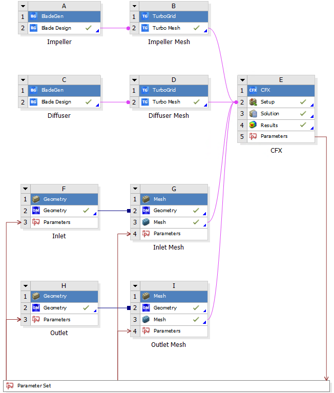 The project diagram in Ansys Workbench.
Inlet and outlet models
The inlet domain represented the flow upon entering the inlet windows in the NeoVAD. The outlet domain represented flow leaving the diffuser towards the outflow tube and the Aorta. Both the inlet and outlet domains were modelled as simple tubes using Ansys Design Modeller and meshed using the Ansys mesh module. It was assumed that the cross-section of these domains was annular, as if a shaft were passed through the entire geometry.
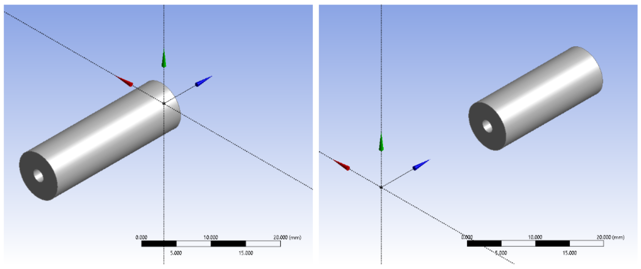 The inlet (left) and outlet (right) geometries in Design Modeller.
The impeller and diffuser lengths were defined as Workbench parameters, and the outlet offset (the distance between the inlet and outlet domains) was defined as the sum of these lengths plus the distance between the impeller and diffuser.
The radius and lengths of the inlet and outlet domains were constant for all simulations. The lengths were set such that the flow was fully developed entering the impeller domain and at the outlet.
| Dimension | Value (mm) |
|---|---|
| Inlet length | 25 |
| Outlet length | 20 |
| Inner radius | 1 |
| Outer radius | 3.9 |
Note
The outer radius used in this analysis was larger than the ideal maximum value for the NeoVAD, which was 3.5mm (24). This may not be significant compared to other simplifications but should be considered for any future work or experimental comparison.
Impeller and diffuser blade models
The initial blade parameters were obtained using Mean-Line Theory conducted by the Texas Heart Institute gor a flow rate of 1 L/min across a pressure head of 60mmHg. The pump speed, diameter, and required pressure head were used to calculate the blade angles.
| Blade parameter | Value (degrees) |
|---|---|
| Impeller inlet angle β1 | 7.5 |
| Impeller outlet angle β2 | 46.7 |
| Diffuser inlet angle α2 | 8.5 |
Using these values, and an initial estimate of 8mm and 8.5mm for the impeller and diffuser lengths respectively, the geometries were modelled using Ansys BladeGen and meshed using TurboGrid.
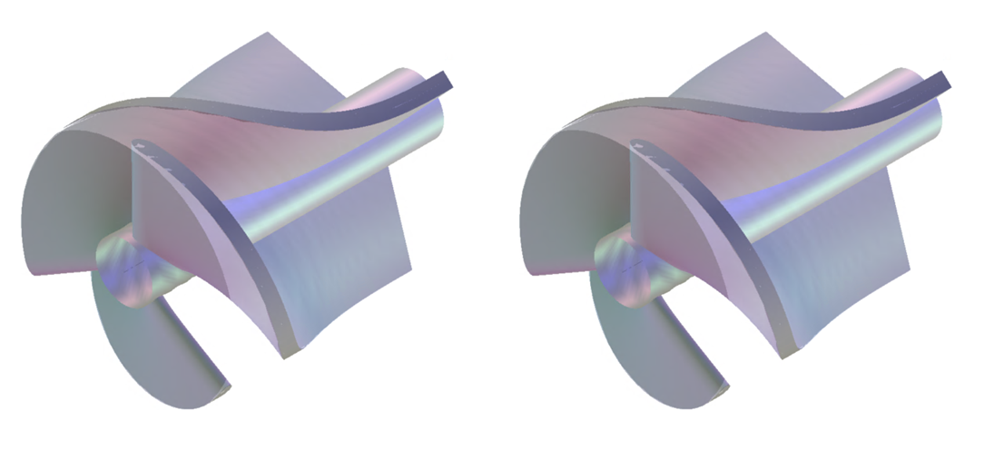 The impeller (left) and diffuser (right) geometries generated using BladeGen.
The four geometries were imported into Ansys CFX, and their respective domains were generated. BladeGen exported a single blade, so they were duplicated, transformed, and interfaced with each other.
The impeller domain was set to rotate at 14250 rpm and the frozen-rotor interface was used between the inlet and impeller, and impeller and diffuser domains. The inlet mass flow rate was set as 0.01725 kg/s, and the outlet static pressure was set to 0 Pa.
The blood was modelled as a Newtonian fluid with a constant viscosity and added as a new material to Ansys CFX:
| Parameter name | Value | Units |
|---|---|---|
| Density | 1035 | kg/m3 |
| Dynamic Viscosity | 0.0035 | Pa s |
| Molar Mass | 65000 | kg/kmol |
| Heat Capacity | 4181.7 | J/kg/K |
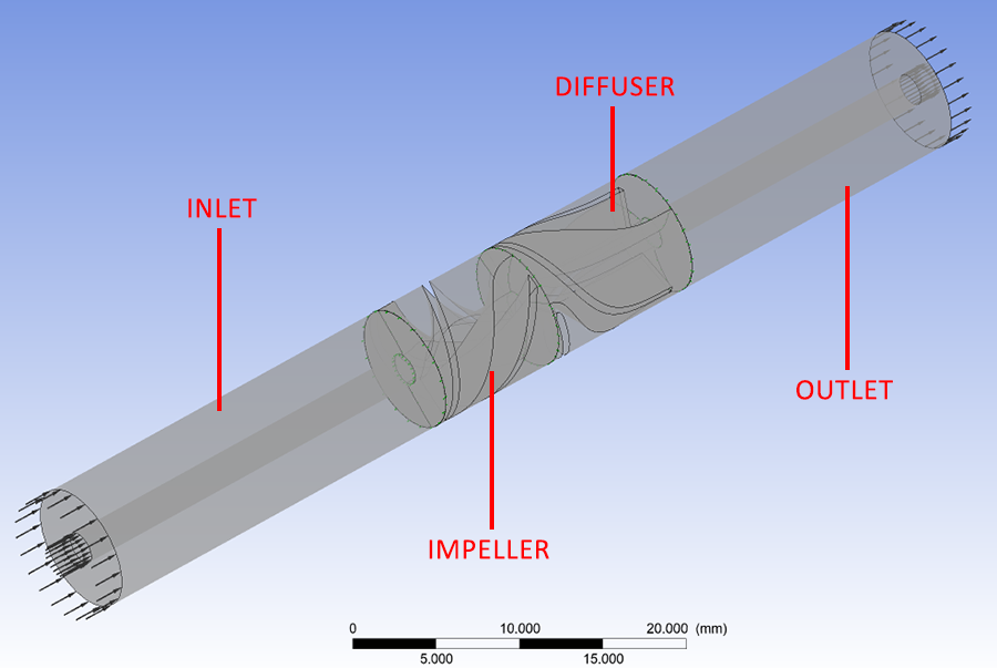 The combined model in Ansys CFX.